INDRODUCTION
If you want to know the output of you arduino project from a long distance without any internet connection GSM modules are the best solution for your projects. You can easily interact with your project by sending and recieving sms or alert calls etc.
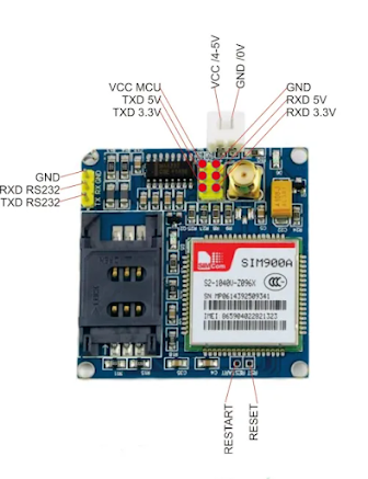
SIM900 GSM/GPRS Module is a GSM modem, which can be integrated into a great number of IoT projects very easily.you can use this module for SMS text messages, Make or receive phone calls, connecting to internet through GPRS, TCP/IP, and more! . SIM900A GSM Module is a dual-band GSM/GPRS engine that works on frequencies EGSM 900MHz and DCS 1800MHz. SIM900A features GPRS multi-slot class 10/ class 8 (optional) and supports the GPRS coding schemes CS-1, CS-2, CS-3 and CS-4. This module can be used in your IoT based projects and embedded systems. This is used in Automobiles, robotics, servers, etc.
HARDWARE OVERVIEW AND SPECIFICATION
The module is powered by a 4.0V to 5v power supply that can deliver up to 2A of current. And it is better tp use a voltage below 4.5v .The communication with this module is done through UART Interface. The data is sent to the module or received from the module through the UART interface. So you can communicate with your controller like Arduino,Raspberry pi with just two or three wires.
- Standard AT commands
- Connect onto any global GSM network with any 2G SIM
- Item Weight: 4.54 g
- Package Dimensions: 12.1 x 10.6 x 0.2 cm
- Adjustable serial baud-rate from 1200 to 115200 bps
- Single supply voltage: 3.4V – 4.5V
- Power saving mode: Typical power consumption in SLEEP mode is 1.5mA
- Frequency bands: SIM900A Dual-band: EGSM900, DCS1800. The SIM900A can search the two frequency bands automatically. The frequency bands also can be set by AT command.
- GSM class: Small MS
- GPRS connectivity: GPRS multi-slot class 10 (default) , GPRS multi-slot class 8 (option)
- Transmitting power: Class 4 (2W) at EGSM 900, Class 1 (1W) at DCS 1800
Datasheet of SIM-900 GSM/GPRS Module
CONNECTING GSM900A WITH ARDUINO
Things Needed
- SIM900A GSM Module and 2G SIM Card
- Arduino (you can use any arduino here I am using Arduino UNO)
- Jumber Wires
- 5V 2A Power supply
Now connect the arduino and GSM according to the circuit diagram
After making circuit diagram insert the SIM card (the card must be 2G supported like VI,BSNL etc) and power up the gsm with the adapter.
Now wait for some time and see the blinking rate of ‘status LED’.Once the connection is established successfully, the status LED will blink continuously every 3 seconds. You may try making a call to the mobile number of the sim card inside GSM module. If you hear a ring back, the gsm module has successfully established network connection.
Software part
AT commands
These are commands which help to communicate with the computer and gsm module.Upload a blank code and open Serial Monitor and type these commands
mySerial.println("ATD+60XXXXXXXXX;");
mySerial.println("ATH");
mySerial.println("AT+CMGF=1"); // Configuring TEXT mode
  updateSerial();
 mySerial.println("AT+CMGS=\"+91xxxxxxxxxx\"");//change 91 with country code and xxxxxxxxxxx with phone number
  updateSerial();
  mySerial.print("Massage from DREAM PROJECT"); //text content
  updateSerial();
  mySerial.write(26);
}
mySerial.println("AT+CNMI=2,2,0,0,0");
Library Used click here to Download
I think you will be undestand all these things below this i have provided another code which you can easily check some of the functions in GSM module by uploading a this program.
Upload the code
#include <SoftwareSerial.h>
SoftwareSerial mySerial(9, 10);
char msg;
char call;

void setup()
{
  mySerial.begin(9600);   // Setting the baud rate of GSM Module
  Serial.begin(9600);    // Setting the baud rate of Serial Monitor (Arduino)
  Serial.println("GSM SIM900A BEGIN");
  Serial.println("Enter character for control option:");
  Serial.println("h : to disconnect a call");
  Serial.println("i : to receive a call");
  Serial.println("s : to send message");
  Serial.println("c : to make a call");
  Serial.println("e : to redial");
  Serial.println();
  delay(100);
}

void loop()
{
  if (Serial.available()>0)
   switch(Serial.read())
  {
    case 's':
      SendMessage();
      break;
    case 'c':
      MakeCall();
      break;
    case 'h':
      HangupCall();
      break;
    case 'e':
      RedialCall();
      break;
    case 'i':
      ReceiveCall();
      break;
  }
 if (mySerial.available()>0)
 Serial.write(mySerial.read());
}

void SendMessage()
{
  mySerial.println("AT+CMGF=1");    //Sets the GSM Module in Text Mode
  delay(1000);  // Delay of 1000 milli seconds or 1 second
  mySerial.println("AT+CMGS=\"+60XXXXXXXXX\"\r"); // Replace x with mobile number
  delay(1000);
  mySerial.println("sim900a sms");// The SMS text you want to send
  delay(100);
   mySerial.println((char)26);// ASCII code of CTRL+Z
  delay(1000);
}

void ReceiveMessage()
{
  mySerial.println("AT+CNMI=2,2,0,0,0"); // AT Command to recieve a live SMS
  delay(1000);
  if (mySerial.available()>0)
  {
    msg=mySerial.read();
    Serial.print(msg);
  }
}

void MakeCall()
{
  mySerial.println("ATD+60XXXXXXXXX;"); // ATDxxxxxxxxxx; -- watch out here for semicolon at the end!!
  Serial.println("Calling  "); // print response over serial port
  delay(1000);
}


void HangupCall()
{
  mySerial.println("ATH");
  Serial.println("Hangup Call");
  delay(1000);
}

void ReceiveCall()
{
  mySerial.println("ATA");
  delay(1000);
  {
    call=mySerial.read();
    Serial.print(call);
  }
}

void RedialCall()
{
  mySerial.println("ATDL");
  Serial.println("Redialing");
  delay(1000);
}


Comments
Post a Comment